Technique to Measure the Longitudinal Resistance
of an Expansion Joint in Service on Tailings Pipeline
Domenico Lanera
IIT Research Institute
January 16, 1998
Abstract
This note describes a technique developed by the author to measure the electrical resistance of an expansion joint in service on a tailings pipeline. The technique provides an indirect measurement of this electrical parameter whiteout interfering with mine operation, such as interrupting tailings pipeline operation and having to disconnect sections of the pipeline. This technique saves considerable amount of time and costs, and may be applicable to similar measurement problems on pipelines.
Background
Tailings are the left over material at an iron mining facility at the end of the ore extraction process. Tailings suspended in water form a slurry that is pumped to settling ponds. The tailings pipelines extend for miles and are made of steel pipe sections (about 2 feet in diameter and 40 feet long) fastened to each other temporarily and resting on wooden blocks a foot off the ground. The temporary hookup results from the need to move pipelines periodically around the tailings basin to spread evenly the tailings as they settle, and to rotate the pipes periodically for evenly distributing the wear caused by the abrasive slurry. Flexible expansion joints are inserted periodically, typically every 2000 feet, to allow the pipeline to expand and move.
The presence of a low-frequency electromagnetic influence, such as that caused by the operation of the Navy's ELF radio transmitters, induces electrical signals onto these pipelines. The resulting voltages on the pipeline, measured to local earth, can be unsafe to the touch for personnel working on the pipeline and, in general, for anybody else that touches the pipelines.
The pipeline sections themselves constitute good electrical conductors. The joints, approximately every 40 feet, may instead be slightly resistive. This characteristic varies from joint to joint, because it depends on the type of mechanical joint in use, the rubber membrane or gasket used to seal the joint, and the alignment of the pipe sections. Pipeline movements resulting from temperature changes and the pressure inside the pipeline also affect the joint resistance. This resistance helps by limiting electromagnetic induction effects.
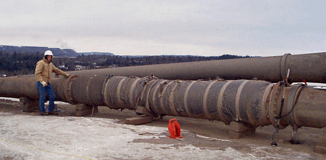
Pipeline expansion joints can have a considerable longitudinal electrical resistance and can be much more helpful in limiting these induction effects; expansion joints can actually block the effects of induction. The expansion joint is made of rubber-like material in the shape of a hose and has metallic nipples with flange or rims at each end so that the joint can be connected to standard metallic pipeline sections, see Figure 1. Spiraling wires may be embedded in the rubbery walls for further strength. The way these wires are terminated at the pipe nipples have a direct effect on the longitudinal resistance measured longitudinally along the joint, between the flanges.
Experience has shown that these expansion joints have enough longitudinal resistance (perhaps above 200 Ohms) to limit induced current and resulting voltages on the pipeline. The industry standard design of including an expansion joint every 2000 feet (600 meters) is sufficient to keep induced voltages to within safe levels where the electromagnetic influence is low to moderate. If requested, manufacturers can ensure that expansion joints have a very large electrical resistance between the flanges. The problem is that the existing joints in use at a mine may be of different vintage and from different manufacturers; consequently their electrical characteristics are unpredictable. The expansion joints themselves are very expensive, costing about $12,000 each. The process of removing and replacing a joint from an active pipeline can be very disruptive to the mine operation. It is also very expensive work, because these expansion joints are not of a standard length, and thus they require custom modifications of the pipeline.
Problem
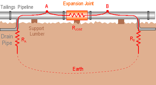
Measuring the longitudinal resistance of an expansion joint when the joint is laying in storage or on the ground awaiting installation is a simple and trivial procedure. The problem is appraising the longitudinal resistance of an expansion joint that is in service, connected into a working pipeline. A simple electrical test across the expansion joint will work in the fortuitous circumstance that the pipeline were electrically floating from earth (sitting on wooden blocks and ignoring capacitive effects). This is not possible literally for the entire pipeline, but may be possible for a pipeline run between expansion joints. In reality, if there are many incidental and unintended electrical groundings of the pipeline this approach becomes unworkable. The problem with pipeline grounds is that they create loops through the earth, around the expansion joint, thus fooling the measurement (see Figure 2).
An in-line expansion joint that is suspected of having inadequate longitudinal resistance presents formidable questions. Requesting pipeline service interruption to take the expansion joint out of the line for testing and possible replacement is a very intrusive and disruptive approach, as well as being very costly. The mine may not allow it at all. It is a very laborious action even if the pipeline is idling. The decision to disconnect and possibly replace an expansion joint has such an impact on mine operation and is so expensive that it requires a commensurate high level of justification. Indirect data and suggestive evidence may not be sufficient when so much is at stake. What is needed is a means of making direct measurements or estimates of what is the longitudinal resistance of an expansion joint while it is in service on a pipeline.
Solution
A solution to the problem is suggested by the ground connection described above between the tailings pipeline and earth (see Figure 2). A Thevenin equivalent circuit can be established between the two points, one on each side of the expansion joint, where the pipeline is connected to earth. A first measurement can be made between these two points (referred here as A and B) to determine the Thevenin impedance ZAB. This impedance is made up of two components in parallel (ZAB = Rjoint // RA-earth-B), as illustrated in Figures 3 and 4. One is the longitudinal resistance of the expansion joint, Rjoint, and the other is impedance of the loop formed by the two earth contacts and the earth itself (RA-earth-B = RA + Rearth + RB = RA + RB, with Rearth = 0). If RA and RB were known, then Rjointcan be derived mathematically from these relationships. It is worthwhile, therefore, to explore possible ways to measure RA and RB.
Incidentally, it should be noted that the earth contacts at A and B may each in reality be a parallel combination of pipeline g rounding present on the respective side of the expansion joint. It is important to inspect the pipeline and determine the nature of all these grounds, to correlate qualitatively the final data later on.
A third point C can be established by driving a ground rod into the earth away from the expansion joint, as shown in Figure 3. This reference rod simulates the connection to remote earth, and it is important that this electrode have a good contact to earth. The resistance of the grounding point C, RC, should be measured using an independent technique, such as the fall-of-potential earth resistance measurement method.

The equivalent lump-form circuit diagram is shown in Figure 4. It shows an electrical loop with three unknown elements, but three possible measurements.
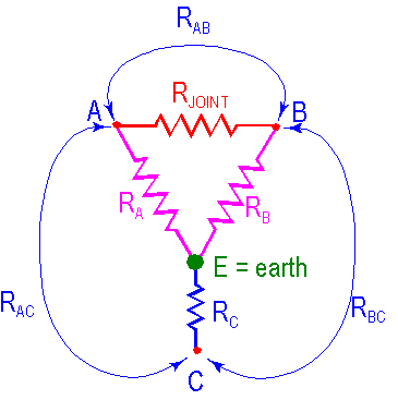
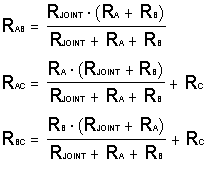
Loop impedance measurements can be made between points A and C, and between points B and C, in the same manner as it was done for ZAB above. The measured loop impedances are then ZAB, ZAC, and ZBC. Since these are mostly resistive they are referred simply as RAB, RAC, and RBC. The equations that relate the individual resistances RJOINT, RA, RB, and RC, to the loop resistances can be derived from the equivalent circuit diagram of Figure 4; they are as follow:
It is a system of three equations with three unknowns, Rjoint, RA, and RB. The following intermediate values x, y, and z, act as dummy variables in the solution process.

The solution for RJOINT, RA, and RB, based on the set of equations shown above and utilizing the intermediate dummy variables are:

These formulas, together with the loop measurements described above
provide a solution to the problem of determining the longitudinal
impedance of an expansion joint in service on a pipeline.
The technique was used in a real situation at Empire Mine in Upper
Michigan, on January 8, 1998. An expansion joint (shown in Figure 1)
was present on a
tailings pipeline right after a booster pump, and was suspected
of having little or no electrical longitudinal resistance.
A reference ground electrode was installed
in the tailings basin itself, a few hundred feet away. The technique
outlined in this note was utilized. The actual
measurements were RC = 163 Ohms, RAB = 4.9 Ohms,
RAC = 185 Ohms, RBC = 189 Ohms. The longitudinal
resistance of the expansion joint, RJOINT, was then calculated
to be 5.04 Ohms.
A recommendation was made
to the mine to replace the expansion joint.
One important note is that the electrode C should have a low resistance
to earth for this method to yield useful results. The magnitude of RC
compared to the desired quantity RJOINT affects
the precision of RJOINT. Efforts should be made to obtain
a good ground at C. Improvements can be made to the ground at C, and
the whole process repeated, if the initial test provides poor results.